Your First Fractal Cloud Deployment with GUI
Target Audience: Platform Engineers, Architects, and Ops Leads
Goal: A comprehensive guide to designing the "Pilot Project" architecture (Cluster + App + DB) using the Fractal Cloud Web Console, mirroring the code-based workflow visually.
Part 1: Core Concepts & Architecture
Fractal Cloud facilitates a Component-Based Infrastructure approach.
While the SDK allows for "Infrastructure as Code", the Web Console provides a Design Canvas to visualize and compose these components.
The Fractal Object Model
- Atom: A reusable infrastructure component (e.g., GKE Cluster, RDS Instance) with embedded standards.
- Fractal (Blueprint): A reusable, governed architecture pattern composed of connected Atoms.
- Live System: The running instance of a Fractal Blueprint, provisioned on a real cloud provider.
Operational Boundaries
- Resource Group: A logical container for ownership and governance. It acts as a Bounded Context, isolating your Fractals and Live Systems to ensure consistent policy enforcement within a specific business domain.
- Environment: A segment of your IT Landscape (e.g., "GCP Dev", "AWS Prod") on which systems are deployed. It maps to one (or more) specific Cloud Provider target (e.g., a GCP Project or AWS Account), establishing the physical deployment boundary.
- Automaton: The orchestration engine. It performs state reconciliation, calculating the diff between your code (The Fractal) and the actual cloud state, ensuring the Live System matches the desired state.
Part 2: The Pilot Project Scenario
We will implement a standard 3-Tier Architecture for a "Pilot Project" using the Fractal GUI (Prefer a code-first approach? Check out the Your First Fractal Cloud Deployment with SDK tutorial to build this exact stack using the Coding SDK).
The stack consists of:
- Compute: A Google Kubernetes Engine (GKE) Cluster
- Data: A managed PostgreSQL Database
- Workload: A Web Application deployed onto the cluster
Part 3: Implementation Workflow
Phase A: The Ops Engineer (Setting the Foundation)
Goal: Define where the infrastructure lives and set security boundaries.
The Ops Engineer uses the Console to map a Fractal Environment to a specific Cloud Provider account (e.g., GCP Project).
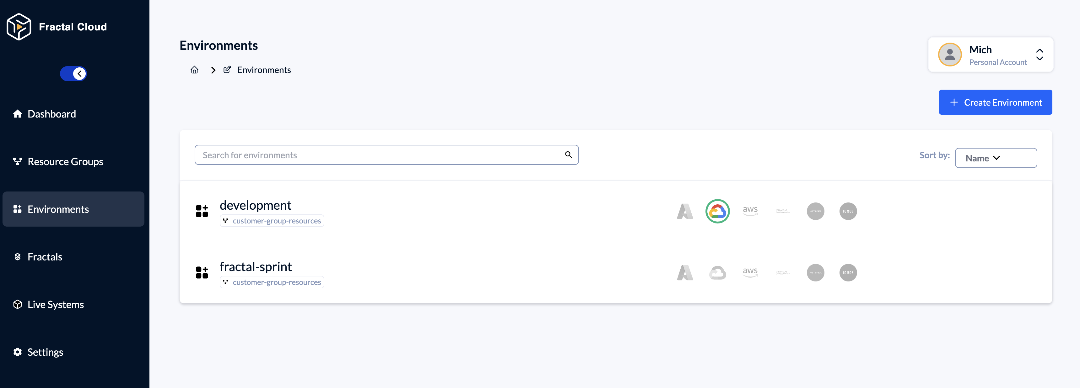
Step 1: Connect Cloud Provider & Define Environment
- Navigate to
Environmentscreate or choose and Environment. - Inside the Environment go to the
Cloud Agentssection and click Initialize Cloud Agent. - Choose the Cloud Provider and follow the istructions.
Phase B: The Platform Engineer (Building Standards)
Goal: Create "Golden Paths" (Standardized Components) visually.
The Platform Engineer uses the Design Canvas to create the Blueprint.
This replaces writing the Java/C# class definitions manually.
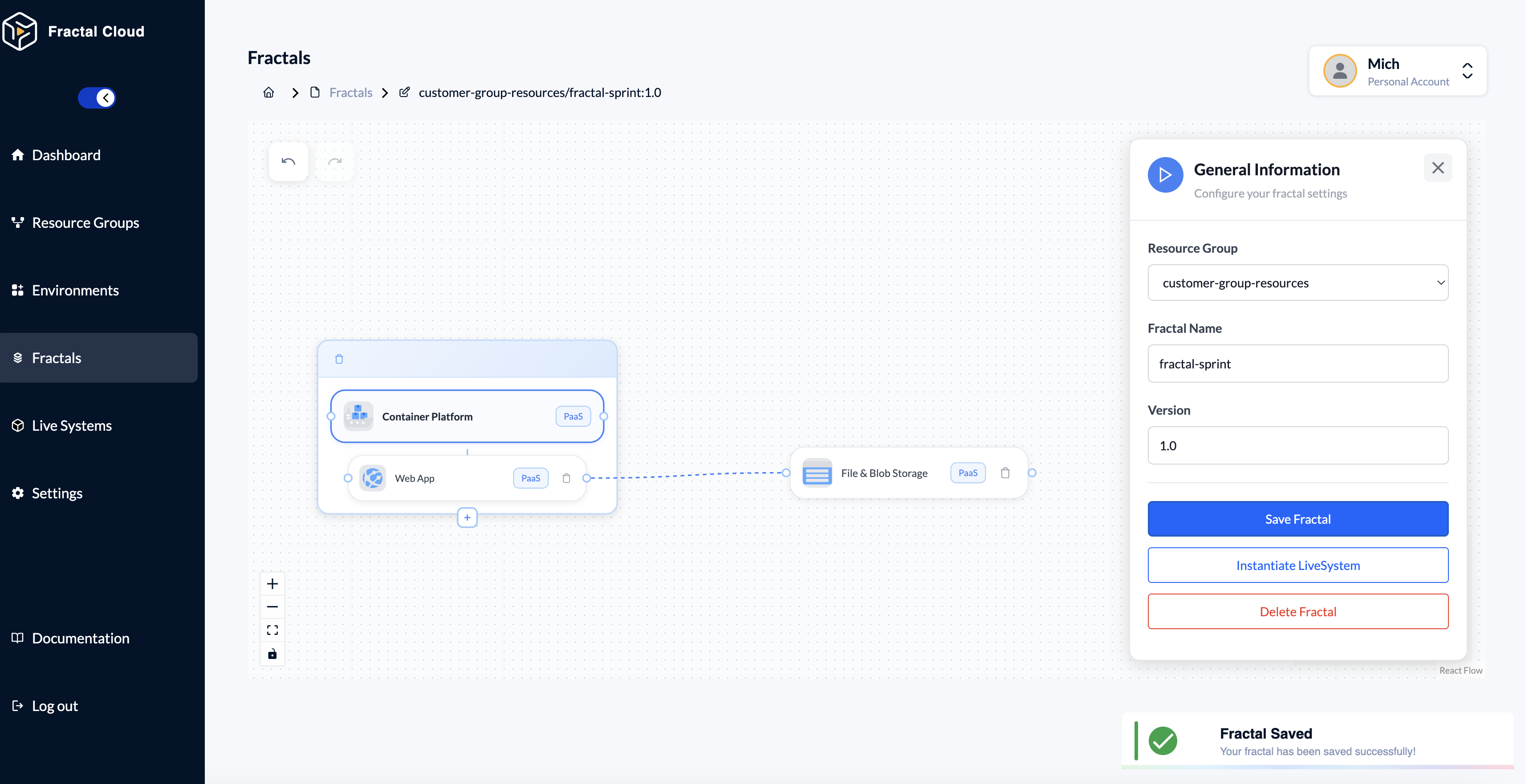
Step 2: Create the Fractal & Define Compute
- Navigate to
Fractals > Create Fractal - Open the Design Canvas
- Drag the Container Platform element from the palette
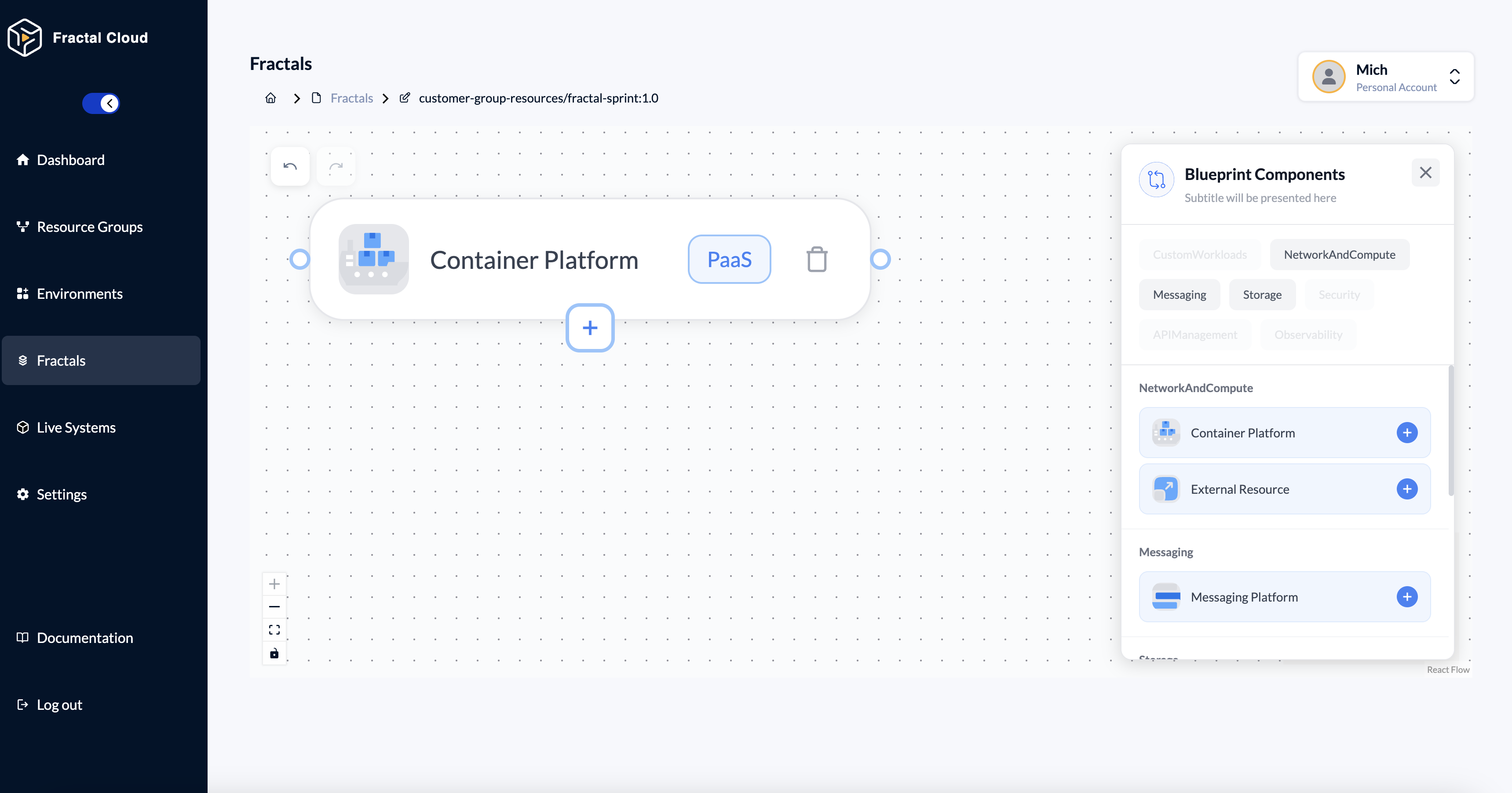
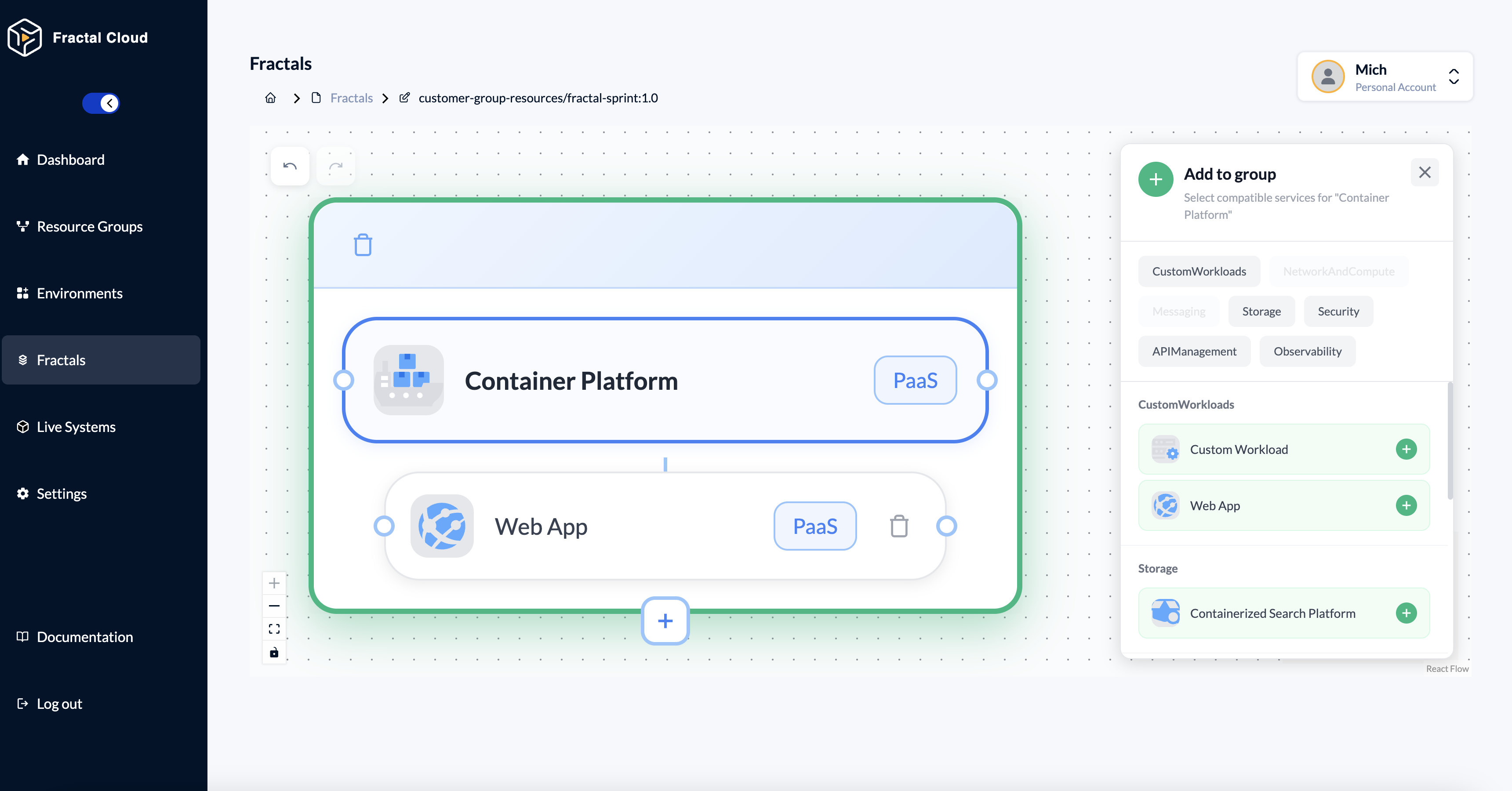
Step 3: Add Workload to Container Platform
- Hover over the Container Platform on the canvas.
- Click the + icon at the bottom of the group box.
- In the side panel, navigate to "CustomWorkloads"
- Select Web App from the list.
The Web App is now nested inside the Container Platform group.
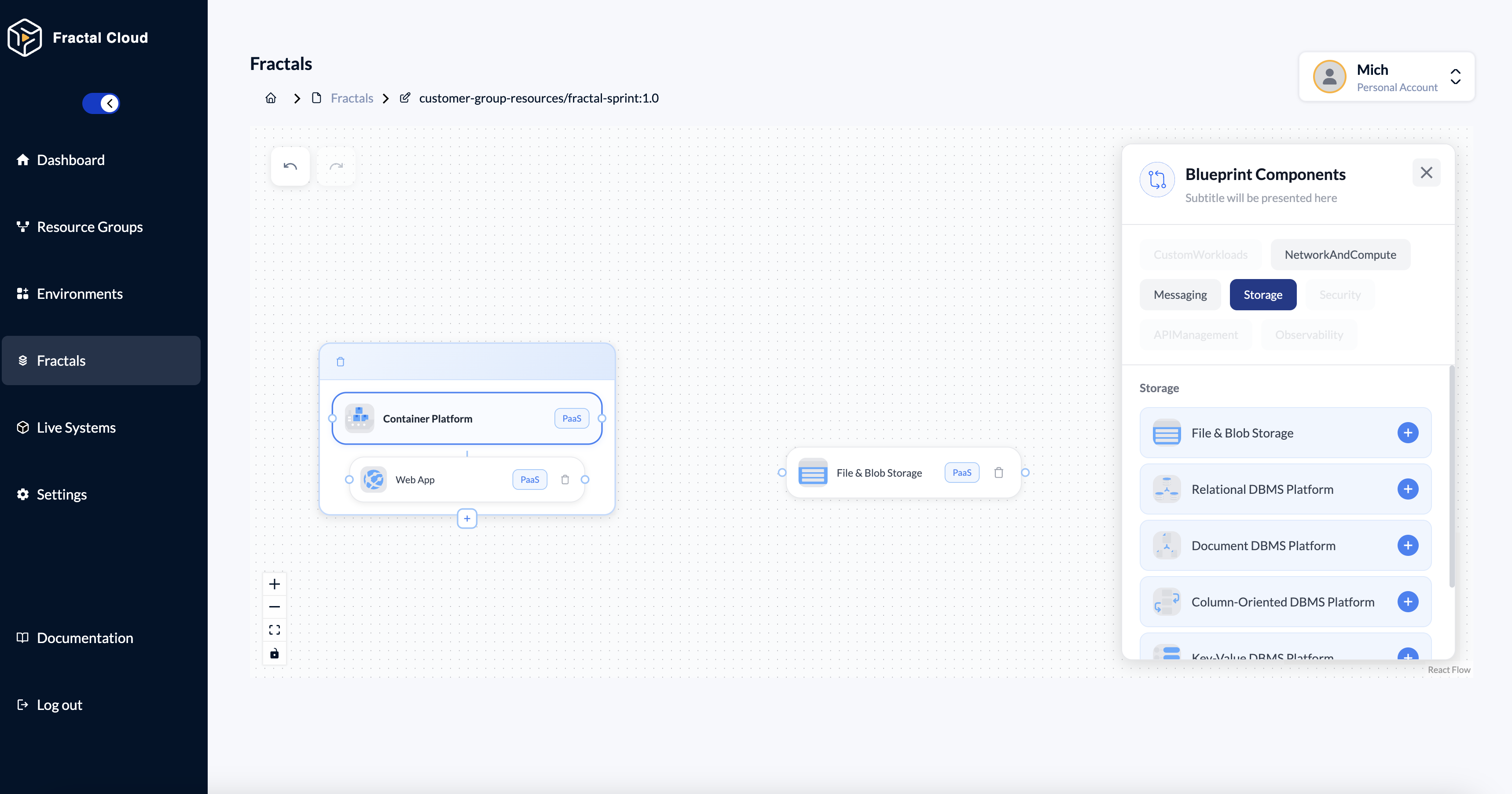
Step 3: Define Storage
- Drag aand a Web Application onto the canvas
- In the Design Canvas, choose to the Storage category.
- Drag the File & Blob Storage element from the palete
Phase C: The Developer (Consuming Infrastructure)
Goal: Deploy the application without waiting for tickets.
The Developer finds this Blueprint in the catalog and instantiates it.
They don't see the canvas; they interact with a simplified Wizard.
Note: Developers interact with a simplified Wizard rather than the full Design Canvas.
This ensures they can deploy infrastructure without accidentally editing or breaking the Blueprint's governance rules.
Step 4: Select & Instantiate
- Find
fractal-pilot-v1in the Fractals list - Open the fractal already defined.
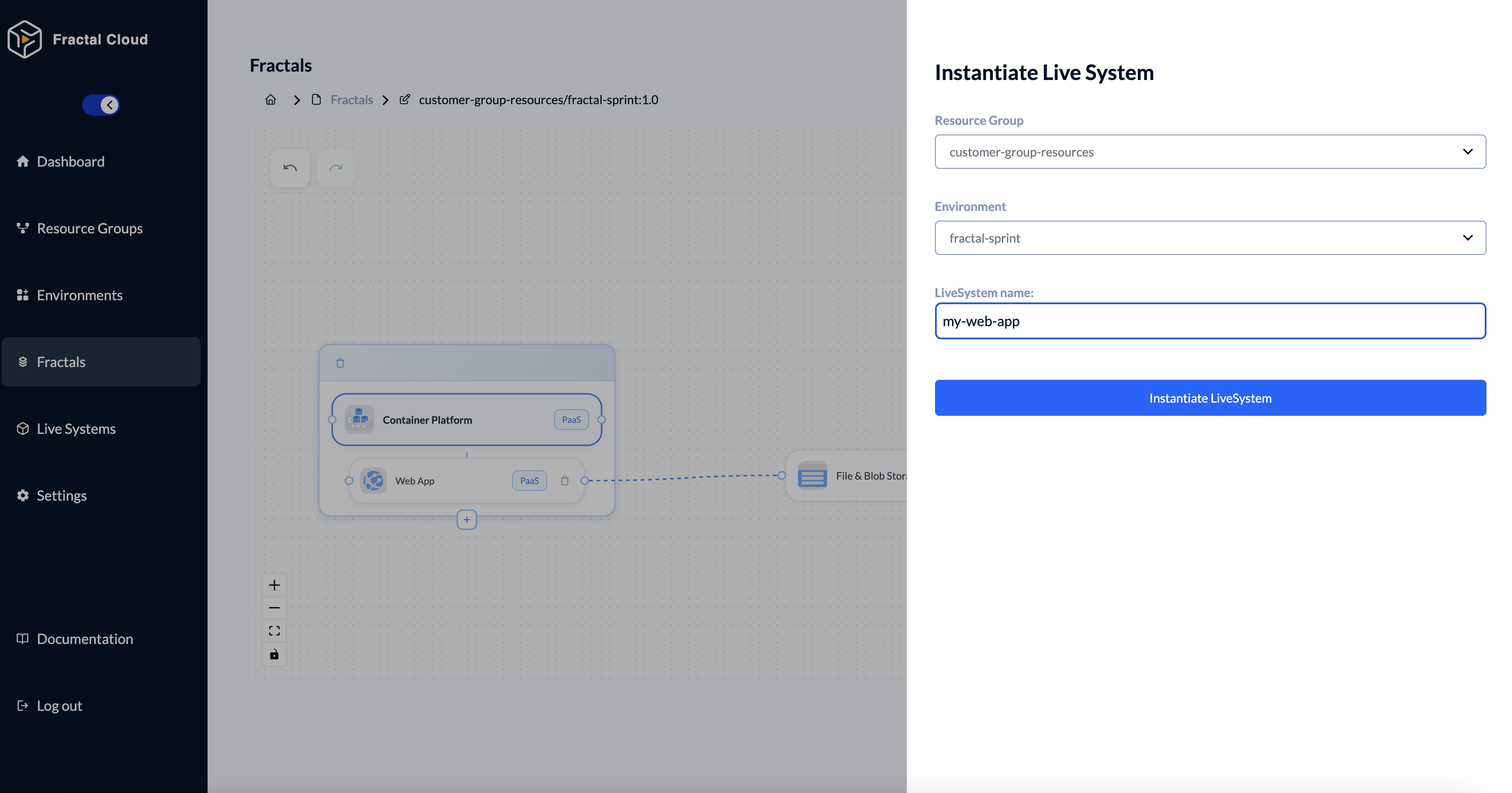
Step 5: Configure & Deploy
- Click on the Play Button on the right
- Then Save Fractal
- Then Instantiate Live System
- Select the +Resource Group*
- Select the Environment, you created earlier (in Phase A, by the Ops Engineer).This environment already has a cloud provider integration configured
- Name your Live System
- Click "Instantiate LiveSystem"
Now you can trigger the deployment. This action starts the reconciliation loop and provisions the infrastructure as defined in the Fractal Blueprint.
Good to Know
The Fractal Blueprint is created once by the Platform team.
It can be instantiated multiple times by different Developers, across multiple environments, without modification.
Summary: Visual vs Code
| Feature | GUI (Console) | SDK (Code) |
|---|---|---|
| Ops Role | Environments Tab for governance | Environment Class definition |
| Platform Role | Design Canvas for blueprints | Atom / Fractal Class definitions |
| Developer Role | Instantiation Wizard for deploy | automaton.instantiate() call |
| CI/CD Integration | Manual via Console | Fully automatable via pipelines |
The GUI is perfect for designing and exploring.
The SDK is perfect for automation and GitOps.